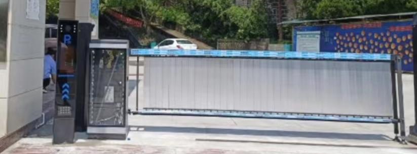
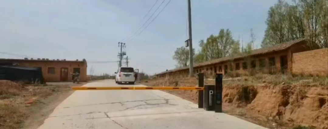
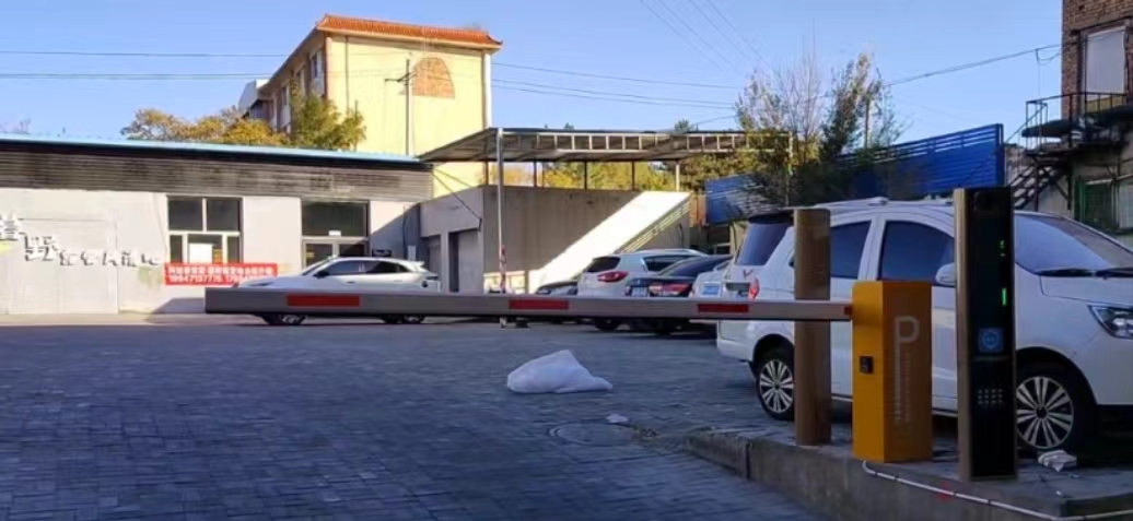
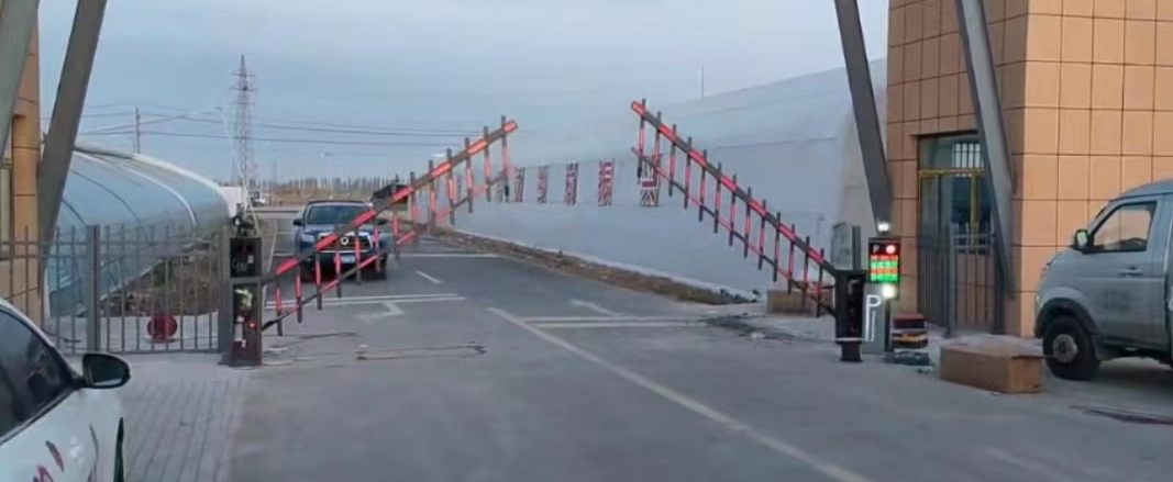
One-in-one-out smart parking lot
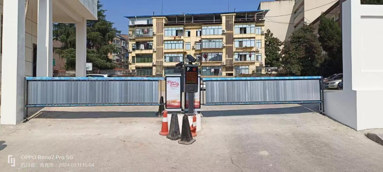
1. Determine the equipment placement according to the design plan and on-site conditions
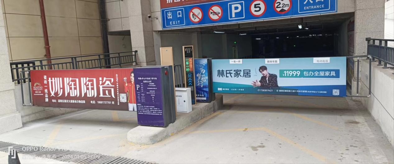
(1) When determining the placement of the gate and card reader, the width of the lane should be ensured first, so that vehicles can enter and exit smoothly. The lane width is generally not less than 2.5 meters, and about 3.5 meters is appropriate. The distance between the card reader and the gate is generally 2.5 meters, and the close distance is not less than 2 meters, mainly to prevent the front of the vehicle from touching the railing when reading the card. For underground parking lots, the card reader should be placed on a relatively horizontal ground as much as possible, otherwise it will be more troublesome for vehicles to park and read the card when going up and downhill. For underground parking lots, if there is an obstacle above the gate, a folding-bar gate should be used, and the height of the obstacle -1.2 meters is the folding point. The placement of the gate and card reader is directly related to whether it is convenient for users to use. Once the position is determined and the pipeline is in place, changing the position will bring great trouble to the construction. Therefore, for engineers who do not have much experience in this area, they should first install the gate and card reader in place, then simulate the user, and check with the Party A personnel whether the positioning is appropriate, and then lay the pipeline.
(2) Determine the license plate recognition installation location.
The viewing angle of the import and export camera is mainly aimed at reading the license plate position of the vehicle entering and leaving. Generally, an automatic aperture lens is selected and the installation height is generally 2-2.5 meters;
(3) Determine the location of the post office (it can be used or not according to the needs of the site)
For parking lots without temporary vehicles, the location of the guardhouse depends on the site, or there may be no guardhouse at all; for parking lots with temporary vehicles, the guardhouse is generally placed at the exit to facilitate charging;
Since the guard room is used to house control computers and other equipment, and is also the workplace for on-duty personnel, there are requirements for the area of the guard room, which should not be less than 4 square meters;
(4) Determine the location of the control host
The control host is the core control unit of the entire parking system and is usually installed in the ticket box.
1. Parking system design parameters:
a. License plate recognition (center distance) and gate (center distance)>0.3M;
b. Management computer (usually placed in the parking lot management booth).
c. Camera installation height: 2-2.5M;
d. Ground sensor coil size: 2M (length) X0.8M (width); generally 4 circles are required.
e. The area of the toll management booth cannot be less than: 4 square meters (2M*2M);
f. Entry and exit lane width:>3M;
g. Equipment installation base size: 0.4M (length)*0.4M (width); the base can also be omitted.
2. Pipeline laying
Pipeline laying is relatively simple. Before laying the pipeline, refer to the parking system schematic diagram and pipeline diagram to clarify the signal properties, signal flow and power supply conditions of each equipment; signal lines and power lines must be laid in separate pipes. For power lines, lines of different voltage levels and current levels cannot be laid in the same pipe.
Burying of ground sensor coils: The burial of ground sensor coils is generally carried out simultaneously with pipeline laying. For specific methods, please refer to relevant drawings.
All wire models of parking system:
(1). Communication line (management computer to entrance and exit machine): RVVP6*0.3mm2
(2). Control line (entrance and exit machine to gate): RVVP6*0.3mm2
(3). Video line (entrance and exit camera to management computer): 75-5 coaxial cable
(4). Ground sensing line: high temperature and corrosion resistant single-strand multi-core 1.5mm2 wire wound 4 times, buried depth 75px-125px;
(5). Power line: (power supply to card reader, gate, camera) RVV3*2.5 mm2;
3. Equipment installation and wiring (see installation diagram and wiring diagram for details)
(1) Installation of entrance and exit machines and gates:
a. Cast a 10-20CM high waterproof and anti-collision safety island (installation base), and pre-bury pipelines in the middle of the entrance and exit machine and gate base
b. Use four expansion bolts to fix the entrance and exit machine and gate on the safety island.
(2) Burying of ground sensor coil:
a. The ground sensor coil is buried after the entrance and exit lane pavement is completed or at the same time as the pavement is paved;
b. When the pavement is paved or is being paved, cut a coil placement groove on the lane near the entrance and exit machine and the gate installation location (the coil is placed in the groove, the groove width is 1.5CM), and the ground sensor coil size is 200CM (length) X80CM (width) X5CM (depth);
c. Wrap the ground sensor wire along the groove for 3 turns, and introduce the two terminals of the coil into the chassis of the entrance and exit machine and the gate, and fill the groove with cement or asphalt.
Single-channel simultaneous entry and exit license plate recognition: